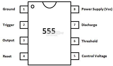

Output Voltage Drop (High), Isource = 200mA, 12.5V typ. With anything but the very very tiniest microcontrollers you get another timer module that can generate interrupts at fixed intervals, making programming this very easy.Where's that come from? This, from the horse's mouth (TI/National's LM version), Headlined, "Output Can Source or Sink 200mA" Data: Output Voltage Drop (Low), Isink = 200mA, 2.5V typ.

Basically, a PWM-based Digital-to-Analog converter.Īnd instead of externally modulating a square wave with that DC voltage, I'd simply tell the microcontroller to set the PWM's duty cycle to 0 for when my square wave is supposed to be low, and to it's current (decaying) duty cycle when it's high. So, I'd simply use a microcontroller with a feasibly fast PWM unit (practically all you'd buy in an actual enclosure have one), and use that with a programmatically reduced duty cycle as the envelope function – a simple low-pass filter (RC) will convert the PWM, being much faster than what the human ear could perceive, to a DC voltage. I find it easier to build digital circuitry instead analog one, and it makes it easier to be exact and power-saving – with fewer components. If you need an appropriately set square wave, or easy adjustability, it's almost certainly not the way to go, in my opinion. When you actually need something like a sawtooth, it's nice.
#555 TIMER DRIVING SPEAKER HOW TO#
I agree it's a nice little IC to build timers, oscillators of all kinds, but in this time and age, its price is rivaled by microcontrollers, which, once you've learned how to program them, make design considerably easier. But square waves don't really call for "correct" or "clean" amplification, do they? The lower that gets, the smaller the ratio of output- to input voltage of that divider!īecause, as said, we don't want DC to flow through the speaker, we then pass the result through C3.Ĭongratulations! The simplest possible voltage controlled amplifier :) Note that this isn't even remotely linear in amplification. So what our signal now sees, after "coming out" of C2 is a voltage divider formed by R5 and Q1's collector-emitter resistance. When the current flowing into Q1's base (from the "capacitor's voltage" node through R2) is high, that resistance becomes low – in fact, significantly lower than R3 or R4. The variable attenuation happens because parallel to R3, we have Q1's collector-emitter resistance. Then you couple in your signal through C2 and R5 – this "pulls" that 4.5V up and down with the high-passed input signal. So what happens here is that you first have R3/R4 forming a voltage divider – so if there was nothing else, the collector point of Q1 would be at exactly 4.5V. Don't worry about this changing your signal – it does – because your speaker doesn't care (or like) DC, anyway. DC can't go through), and the frequencies at which that circuit cuts off depend on the values of C2 and R5, and also on C3 – you can safely make C3 a lot bigger than 100nF. Notice that I used C2 to capacitively couple your square wave into the circuit, and C3 to couple it out – that forms a high pass filter (i.e. Simulate this circuit – Schematic created using CircuitLab That would attenuate the input signal with rising voltage. That, in turn, I would connect to the base of an NPN transistor (possibly with a bigger base resistor not to distort the voltage curve too much) in common-emitter configuration. To be fair, instead of your envelope circuit that decreases the output, I'd simply charge a capacitor through a resistor that leads to a \$1-e^\$ kind of voltage over the capacitor.
#555 TIMER DRIVING SPEAKER GENERATOR#
You could use the output of your envelope generator to drive the base of a transistor which amplifies the square wave signal. This isn't necessary to get sound out of the speaker, but will make the sound a little louder than if R2 was not there (replaced by a short). Second, R2 causes the current decay when Q1 is shut off to have about the same profile as the current rise when Q1 is turned on.

First, they give the inductive flyback current a place to go when Q1 abruptly shuts off. The amplitude of the signal applied to the speaker is a function of the volume adjustment voltage, fed in at top. The transistor will switch on and off according to the square wave. Here is a simple circuit that exploits this effect: However, when you start with a square wave, that is fine. This doesn't work with other waveshapes because the result is clipped tops and bottoms, so you end up with a square wave. Fortunately, this is easy to do with square waves because you can amplify them arbitrarily and then clip at a adjustable level. What you want to do is to amplitude modulate a square wave.


 0 kommentar(er)
